



After equipment is put into use, the quality of maintenance directly determines its lifespan and measurement accuracy. A properly maintained weighing system can easily operate stably for more than five years; conversely, even with appropriate equipment selection, various problems may arise within a year. This article outlines key considerations for practical operation from the perspectives of daily maintenance and troubleshooting.
I. Routine Maintenance: Frequency and Content
Monthly visual inspection
It is recommended that a designated person conduct a monthly inspection of the material tower, checking the following items:
Sensor appearance: Check for obvious deformation, cracks, and corrosion. Outdoor sensors are exposed for long periods of time, and if the protection level is not up to standard or the materials are not properly selected, corrosion is the most common form of degradation.
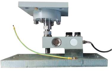
Cable condition: Check for signs of rodent chewing, abrasion, or flattening. Rodent infestations are common in farms, and water ingress and short circuits after cable damage are frequent faults.
Junction box: Check if the cover is loose, if the sealing ring is worn out, and if there are any signs of water ingress. Water ingress into the junction box is one of the most common causes of failure in weighing systems.
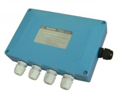
Around the sensor: Are there any accumulated materials or foreign objects causing obstruction? If feed dust accumulates between the sensor and the base, it will affect the sensor's return position, resulting in readings that are too high or too low.
Clean up accumulated materials quarterly.
Feed dust, mud, and clumps of material accumulating around the sensor should be cleaned up promptly. Use a soft brush or compressed air for cleaning; avoid using a high-pressure water gun to directly wash the sensor. While an IP68 waterproof rating can resist rain immersion, it may not be able to withstand the impact of a high-pressure water jet.
Recalibrated every six months
Sensors subjected to prolonged stress can develop creep, and instrument components may drift with temperature and time. It is recommended to perform zero-point calibration every six months and range calibration annually.
Zero-point calibration procedure: After emptying the silo, find the "Zero-point Calibration" or "Empty Scale" option in the instrument menu, confirm, and the instrument will automatically record the current AD value as the zero-point reference.
Range calibration procedure: Load a weight of known weight or a standard material bag (it is recommended to load a full-range 50% or higher), perform range calibration through the instrument, and the instrument calculates the conversion factor based on the "current AD value" and "known weight".
After calibration, the new parameters are recorded and compared with historical data to assess the sensor's stability trend. If the calibration frequency needs to be significantly reduced (e.g., calibrated every one or two months), it indicates that the sensor may have aged or is faulty.
II. Common Faults and Troubleshooting Steps
Fault 1: The instrument displays "----" or "ERR".
Possible cause: Abnormal sensor signal, instrument cannot detect valid input.
Investigation steps:
First, check the junction box – open it and check for water ingress and loose terminals. This is the most common cause.
If the junction box is normal, use a multimeter to measure the sensor output: there should be a 5-10V excitation voltage between the red and black wires, and a millivolt-level signal between the green and white wires (close to 0mV under no-load, changing after loading). A signal of 0 or abnormal fluctuation indicates an open circuit in the sensor or wiring.
Fault 2: Reading is not zero when the tower is empty.
Possible causes: zero drift, foreign objects stuck around the sensor, or material buildup at pipe connections.
Investigation steps:
Confirm that the silo is indeed empty – sometimes there is material buildup at the pipe connections, making it appear empty when it is actually still there.
Check for any foreign objects obstructing the sensor.
If there are no problems, perform "zero point calibration" in the instrument menu to recalibrate the empty scale status.
Special note: If the drifting occurs every time it rains, it is most likely that water has entered the junction box.
Fault 3: The reading fluctuates wildly, and the number continues to oscillate.
Possible causes: vibration interference, poor grounding, moisture in the junction box, or weak filter parameter settings.
Investigation steps:
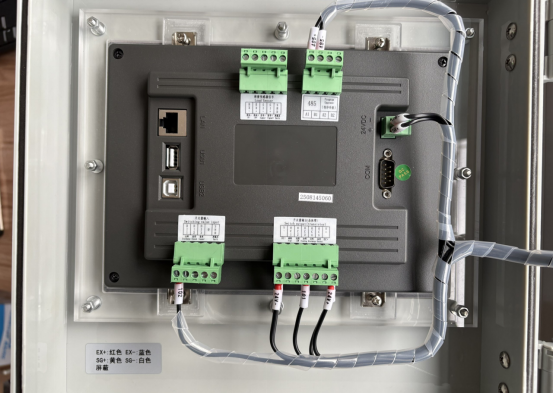
Try increasing the instrument's filter strength. The Zhongke Huigan SM40 series instrument has adjustable filter parameters; increase it by one level and observe the effect.
Check the grounding of the shielding wire—the shielding layer must be grounded at one end of the instrument; grounding at both ends will cause ground loop interference.
Check if the junction box is damp.
Check for any new sources of vibration (such as newly installed fans placed directly next to the material tower).
Fault 4: The reading after loading does not match the actual value (too high or too low).
Possible causes: range calibration failure, uneven force on the sensor, or external force acting on the silo.
Investigation steps:
Check the silo for any additional connections—whether the feed and discharge pipes are rigidly connected to the silo. Rigid connections cause some force to be transmitted to the ground through the pipes, and the sensors will only detect a portion of the weight. Flexible connections must be used for the pipes.
Check if the force on each sensor is uniform. Use the angle difference function on the instrument to observe whether the output values of each sensor are close. Under empty tower conditions, the difference in sensor readings should be within ±5%. If the difference is too large, fine-tune the height using the adjusting bolts on the module.
Recalibrate the range.
Fault 5: Communication failed, data cannot be transmitted to the central control unit.
Possible causes: incorrect parameter settings, reversed wiring sequence, or device address conflict.
Investigation steps:
Verify that the instrument address, baud rate, and data format are completely consistent with the settings of the central control system.
Check if the A/B pin sequence of the 485 bus is reversed (A to A, B to B).
For long-distance communication, check if a 120Ω terminating resistor has been added at the end.
Disconnect the devices one by one to check for address conflicts (addresses on the same bus cannot be duplicated).
III. Quick Troubleshooting Checklist
Prioritize investigating the phenomena, then investigate the secondary phenomena.
The indicator shows ERR/No Signal. It may also indicate whether the junction box is infiltrated or if the sensor cable is broken.
The empty tower reading is not zero. Is there any foreign object obstructing the sensor? Perform zero-point calibration.
Severe reading fluctuations may indicate that filter parameters are set too low or that the shielding wire is properly grounded.
Inaccurate readings after loading: Is the pipe connection a hard connection? Has the range calibration failed?
Communication failure address/baud rate settings; Are A/B lines reversed?
IV. When is it necessary to replace the sensor?
The following conditions indicate that the sensor is damaged or its performance has been severely degraded, and replacement should be considered:
Obvious damage to appearance: cracks in the casing, severe deformation, and rust perforation.
Decreased insulation resistance: Use a megohmmeter to measure the insulation resistance between the sensor and the housing. If it is less than 50MΩ, it indicates that the inside is damp.
The output signal is severely nonlinear: the reading is acceptable when the weight is small, but the deviation increases significantly when the weight is large, indicating that the strain gauge is aging or damaged.
Drifting persists even after repeated calibration: Significant drift reappeared the day after calibration, even though there were no issues with the junction box or grounding, indicating that the sensor's stability had failed.
When replacing sensors, it is recommended to replace the entire set of modules from the same batch to ensure parameter consistency among the four sensors. Replacing only one sensor may lead to mismatched outputs from the individual sensors, affecting overall accuracy.
V. Maintenance Record Recommendations
It is recommended to establish a maintenance file for each weighing tower system, recording the following information:
Basic equipment information: sensor model, instrument model, installation date
Calibration records: Date, zero point value, and range value for each calibration.
Fault record: Fault phenomenon, troubleshooting process, and handling result
Repair record: Replaced parts, replacement date, reason for replacement
Complete maintenance records not only facilitate subsequent troubleshooting, but also provide a basis for equipment life assessment and budget planning.